
Page 38 - ELECTRONICON_DC-Kondensatoren
P. 38
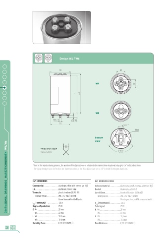
Design W4 / W6
                            W 4    W 6


                                                                     W4


                                                                     W6


                                                                    bottom
                                                                    view
      DIMENSIONAL DRAWINGS_MASSZEICHNUNGEN_W4/W6
                              Principal circuit diagram
                              Prinzipschaltbild


                        * Due to the manufacturing process, the position of the base screws in  relation to the connections may deviate by up to 3.5° in both directions.
                          Fertigungsbedingt kann die Position der Bodenschrauben zu  den Anschlüssen um bis zu 3,5° in beide Richtungen abweichen.


                        E67  CAPACITORS                             E67  KONDENSATOREN

                        Can material .............................aluminium, filled with neutral gas (N )  Gehäusematerial .....................Aluminium, gefüllt mit neutralem Gas (N )
                                                              2                                             2
                        Lid..............................................aluminium, folded edge  Deckel ......................................Aluminium, gebördelt
                        Terminals ..................................plastic insulator (UL94: V0)  Anschlüsse ..............................Kunststoffisolator (UL94: V0)
                             internal thread .......................iM6 × 12 mm (7.5 Nm),       Innengewinde ........................iM6 × 12 mm (7,5 Nm)
                                           tinned brass with nickel barrier           Messing verzinnt, mit Nickelsperrschicht
                        I  (Terminals)   ....................120 A  I  (Anschlüsse) .....................120 A
                         max                                         max
                        Degree of protection ................IP 00  Schutzgrad ...............................IP 00
                        K  W4 .........................................25 mm  K  W4 ........................................25 mm
                             W6 .........................................33 mm       W6 ........................................33 mm
                        L   W4 .........................................19.5 mm  L   W4 ........................................19,5 mm
                             W6 .........................................19.5 mm       W6 ........................................19,5 mm
                        Humidity Class .........................C, TX (IEC 62498-1)  Feuchteklasse .........................C, TX (IEC 62498-1)
        38